Wednesday, February 4, 2015

Upgrading a Cisco IPS

This tutorial will guide you through upgrading the firmware on an IPS (Intrusion Prevention System) sensor. We don't want our systems hacked by Chloe from 24, so we need to keep our stuff in tip-top shape! Onward!

Set it up

Download the image file(s) from support.cisco.com You can up/download them to an FTP, SCP, HTTP, or HTTPS server; provided your sensor can access it.

Pull it down

Log into the sensor via a terminal console (telnet or ssh). In configuration mode, we need to pull the image file we downloaded off our server. This example uses our FTP server:
conf t
upgrade ftp://ftpuser@192.168.1.1/IPS-K9-X.X-X-XX.pkg
You'll be prompted for a password, so put it in
Enter password: ********
Enter yes to complete the upgrade.

The device will pull the image off the server, decompress, install, then reboot. Once rebooted log back in via terminal and check the version.
show ver
And that's it! Chloe can go whine to Jack because she can't get in anymore.


Armageddon (Optional!)

IPS modules are usually in-line, meaning they're the cream filling in our Oreo network. If they go down, everything goes down. So you've unleashed the fires of hell upon earth!

Alright, there's a couple things you can do to prevent this from going four-horsemen bad.

1. Make sure to have someone on site, next to the rack, rearing to go

2. Have a cabling contingency; so you can bypass the failed IPS

3. Have another IPS to swap in!

Even with all that, you'll need to get it back to a clean-working state. For this we'll need ROMMON (woo!)

Gather

ROMMON is the boot-loader of an Cisco device, much like on an Android phone. It allows you to manage system files without booting into the OS. Download the IPS system image file to the tftp root directory of a TFTP server that is accessible from your IPS. Make sure you can access the TFTP server location from the network connected to the Ethernet port of your IPS.

Press Break or Esc at the following prompt while the system is booting to interrupt boot. Press the spacebar to begin boot immediately.

You have ten seconds to press Break or Esc.
Use BREAK or ESC to interrupt boot.
Use SPACE to begin boot immediately.
The system enters ROMMON mode. The rommon> prompt appears.

Check the current network settings.
rommon> set
ROMMON Variable Settings:
ADDRESS=0.0.0.0
SERVER=0.0.0.0
GATEWAY=0.0.0.0
PORT=Management0/0
VLAN=untagged
IMAGE=
CONFIG=
The variables have the following definitions:
Address: Local IP address of IPS
Server: TFTP server IP address where the application image is stored
Gateway: Gateway IP address used by IPS
Port: Ethernet interface used for IPS management
VLAN: VLAN ID number (leave as untagged)
Image: System image file/path name Config—Unused by these platforms

Not all values are required to establish network connectivity. The address, server, gateway, and image values are required.

The default interface used for TFTP downloads is Management0/0, which corresponds to the MGMT interface of IPS.

Verify that you have access to the TFTP server by pinging it from your local Ethernet port with one of the following commands.
rommon> ping 192.168.1.1
Define the path and filename on the TFTP file server from which you are downloading the image.
rommon> IMAGE=path/file_name
Caution Make sure that you enter the IMAGE command in all uppercase. You can enter the other ROMMON commands in either lower case or upper case, but the IMAGE command specifically must be all uppercase.

UNIX Example
rommon> IMAGE=/system_images/IPS 4240-K9-sys-1.1-a-7.0-4-E4.img
The path is relative to the default tftpboot directory of the UNIX TFTP server. Images located in the default tftpboot directory do not have any directory names or slashes in the IMAGE specification.

Windows Example
rommon> IMAGE=\system_images\IPS 4240-K9-sys-1.1-a-7.0-4-E4.img
Enter set and press Enter to verify the network settings.

You can use the sync command to store these settings in NVRAM so they are maintained across boots. Otherwise, you must enter this information each time you want to boot an image from ROMMON.

Deploy

Download and install the system image.

rommon> tftp
To avoid corrupting the system image, do not remove power from the IPS while the system image is being installed.

If the network settings are correct, the system downloads and boots the specified image on the IPS. Be sure to use the correct IPS image. And now we're back to square-one, BUT without the fire and brimstone. :)

GRE pass-through on ZBF

Simple little config snippet for a Cisco Zone-Based firewall.

First you need to put in a deny statement for GRE traffic in an ACL.
Deny? Wait a second, don't we want traffic to pass?
Well of course we do! But if you remember in a Zone-Based firewall your outbound ACL is used in a class-map to inspect traffic; dynamically allowing bi-directional sessions. The reason we want to deny it is you can't inspect GRE traffic; it just doesn't work.
(config)#ip access-list extended ACL_PERMIT_GRE
(config-ext-nacl)#deny gre any any

Okay so we're not inspecting traffic, but we still need to pass it. To do this we have make a class-map to nest under out outbound and inbound policy-maps.

Now we'll create our class-map which matches GRE traffic, referencing the ACL we just made:
(config)#class-map type inspect match-all CMAP_PASS_GRE
(config-cmap)#match access-group name ACL_PERMIT_GRE

Then we want to apply this to our policy maps and define the action as pass.
The policy maps I'm applying these to also contain class-maps for generic traffic.
(config)#policy-map type inspect PMAP_UNTRUST_TO_TRUST
(config-pmap)#class type inspect CMAP_PASS_GRE
(config-pmap-c)#pass

(config)#policy-map type inspect PMAP_TRUST_TO_UNTRUST
(config-pmap)#class type inspect CMAP_PASS_GRE
(config-pmap-c)#pass

And that's about it, your GRE should be good to go. This will work for PPTP pass-through on a Cisco IOS running in ZBF and the same principal should apply for an ASA.

Tuesday, September 23, 2014

pfSense on a Firebox Part 2: Snort

The main reason I wanted to install pfSense was for Snort. It turns your firewall into an IPS/IDS system which will utilize Snort's signature database for detection, and the best thing is it's all open-source! Snort is actually now owned by Cisco after their acquisition of Sourcefire last year - hopefully we'll be seeing it pay off when they update their IPS line.

First things first, we need to install the packages, luckily pfSense has a package-manager built in. Navigate to System> Packages and select the Available Packages tab, peruse through the list and find snort and hit install.


While it's installing head over to snort.org and sign up as you need to register to get access to it's signature database. Once you've confirmed your email, click on your username at the top right and go to Oinkcode, you'll see a long hash; keep this tab open as you'll need it once snort is done installing.

After it's done, the first thing you want to do is update it's signature database, to do this go to Services> Snort then select the Global Settings tab. Here you can put your Oinkcode in the corresponding field, select your type of update (snort VRT rules), you can also select update check intervals, I left mine on manual as this isn't a production box - if it was, you'd want it at about once per day. Now go to the Update tab and check for updates; it should take a few minutes to download everything.

Now that you have your updated signature database, you need to bind an interface. This tells snort which interfaces on your box to listen to for signature matches.

Go to Snort Interfaces and select new; you'll see a new list of options come up. Keep your interface as your WAN (unless you want to sniff internal traffic, which isn't always a bad thing, especially when you have a DMZ)

Select Block offenders; an easy practice to tune this is to drop the shun time down to something manageable; if you have perma-blocks on you'll be constantly having to go in and reviewing blocks, this way you can block signature matches and check them later for further investigation - this gives you a bit of peace of mind without being overly paranoid. Back in Global Settings you can select "Remove blocked hosts interval" - I set mine to 1hr as suggested. I left my search method as AC-BNFA because I am definitely using a low end system (1.6GHz Celeron!)

Everything else I also kept as default - for now.

In the WAN Categories tab you can select your IPS policy, or specific rules. I opted to use a pre-defined policy - Balanced. Once you enabled that you can see a list of rules in the WAN Rules tab - balanced enables just over 1500 and disable them as you please.

In the Preproc tab, you can enable Portscan Detection if you so desire - I'm going to leave this blank as I intend on installing Strikeback.


In the Pass Lists tab you can specify your white lists; hosts or subnets which snort will ignore.

Theres a million other settings you can go through that I honestly don't care about for this small project - but if you stop here like I did you should have more than enough protection for a SOHO network :)

You can see any signature detection under the Alerts tab and blocked hosts in the Blocked tab - unfortunately it doesn't look like snort on pfSense can do packet captures like Cisco's IPS's can with Wireshark being built-in.


Wednesday, September 17, 2014

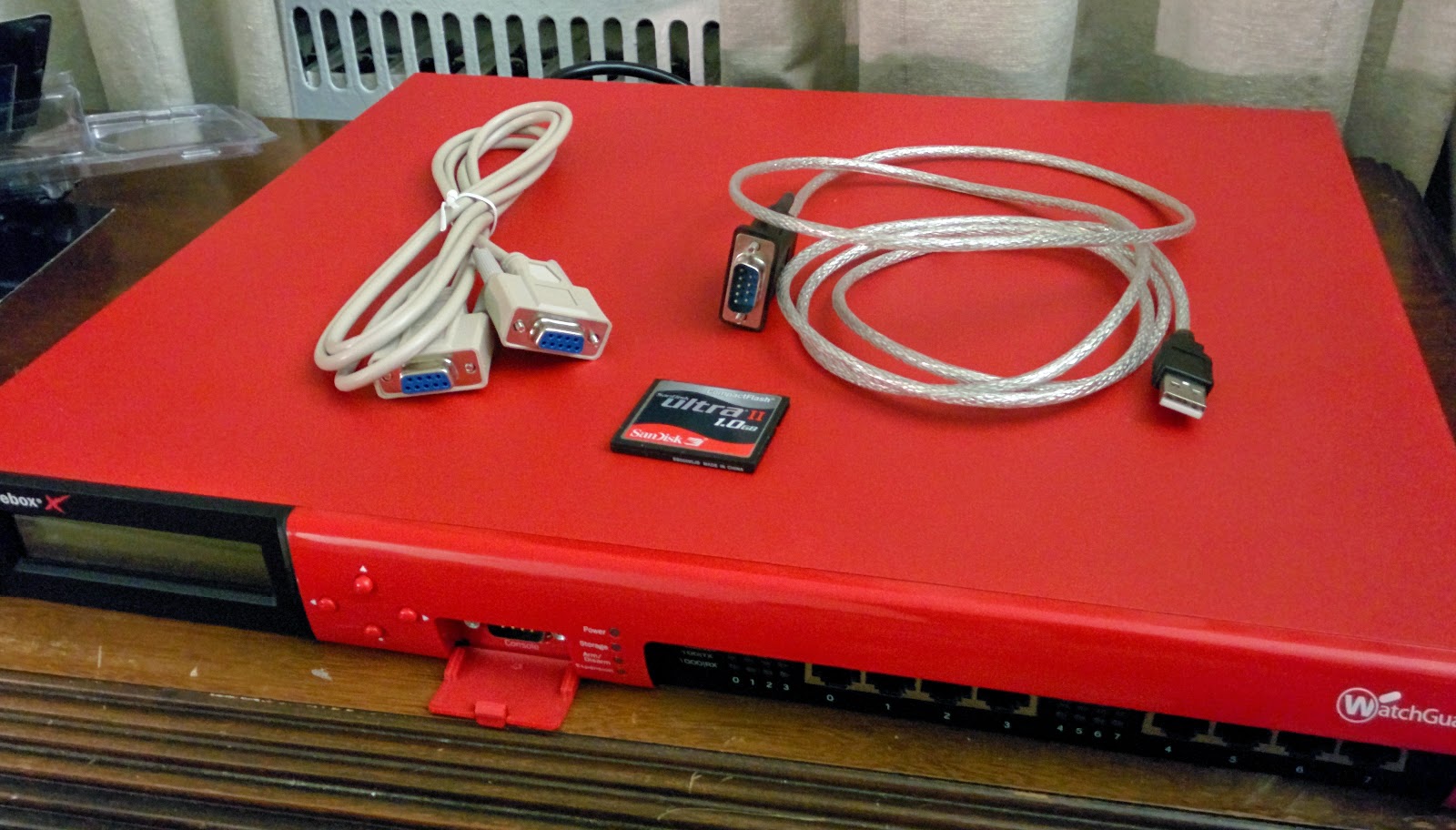
Hacking a Watchguard Firebox into a pfSense firewall


The more I work with Fortigates, the more I like the idea of a UTM - they're streamlined and everything is in one place, managed from a easy-to-access webGUI. I was poking around on eBay for stuff and stumbled upon a Watchguard Firebox x1250e for a reasonable $50 price tag; I thought to myself why not!?. When I got it I fiddled around with Fireware 10.2 which was on it already, and quickly learned why the company I work for doesn't touch these devices - they're terrible to manage. Quickly disappointed, I decided to get pfSense up and running on it - this way I can do whatever I want and indulge the Lego-builder inside me - RAM/CPU upgrades and open source software! Woo!

I found discrepancies between different walkthroughs online on how to go about doing this so I thought it'd be a good idea to jot it all down here; for both your and my benefit.

You can use a 2.5'' HDD or a CF card to boot pfSense - I'm only going to be going over the CF card bit as I didn't have any 2.5's laying around.

On that note, the stock BIOS has an issue where it won't boot CF cards larger than 512MB; unfortunately for me the smallest card I had that I was willing to spare for this project was 1GB. To remedy this, we flash a new BIOS using FreeDOS!

So lets get started!

Rip open the case by removing the 14 screws from the sides/back of the chassis. Remove the stock CF card (mine was a 256MB SanDisk), image the default CF card with FreeDOS (which you can find here.) using the software of your liking; I used Win32DiskImager.

This would be a good time to plug in your USB-to-Serial & Null Modem cables to the Console port on the front of the Firebox - you need a DB9 cross-over cable (aka null modem); female serial will not work. The default settings for most terminal emulators should be fine at this point (I use Tera Term) however the settings you'll need are:
Baud rate: 9600
Date: 8 bit
Parity: none
Stop: 1 bit
Flow control: none
Insert the CF card back into Firebox and power it on

Should see a C:\> prompt
Change to the BIOS directory
Flash the new BIOS with the following command: awdflash x750eb7.bin /py /sn /cc /e
The x750e model is identical to the x1250e
Once the prompt returns, you can power off the device.

While it's powered off , go to the pfSense directory  and download the appropriate and newest image for pfSense, For my 1GB card I downloaded pfSense-2.1.5-RELEASE-1g-i385-nanobsd.img.gz (note the card size referenced in the image name). You can swap out the CF card once you image it.

While it's booting press Tab to enter the BIOS as we're going to need to change some settings (yes it says to hit del but we're going through a terminal emulator, trust me, hit Tab). Select Standard CMOS Features, from here select IDE Channel 0 Master [SanDisk SDCFJ-256] and change the following settings:
IDE Channel 0 Master [Manual]
Access Mode                  [CHS]
Head        [2]
This BIOS does not support thermal-control for the three really noisy fans you might've noticed at the back of the chassis; if you would like to make them a little bit quieter select PC Health Status and set CPU Fan PWM value to [AA] (do not set it to lower than 0xAA [0x00-99] as it wouldn't POST for me and you'll have to reset the CMOS and do everything over again). Caution: adjusting the fans may lead to over-heating if your delta temperatures are already above average.
After you're happy with your settings hit Save and Exit from the main menu.

It should now re-POST then boot straight into pfSense's main menu! Hooray! If you get something that says "Empty or corrupt config.xml" the imaging didn't work or you have a bad CF card. In my case, I had to re-image the disk and it worked the second time around (that's what happens when you're too lazy to check hashes!)


You can go through the small menu to set up the initial interfaces, a note though: it will say you can access the web GUI through the WAN port - this is incorrect, by default it is not allowed for security reasons and you'll have to go in through a trust port (LAN).

Tuesday, August 5, 2014

Site-to-Site VPNs - Part 1: The Basics

I've been getting a lot of questions lately about VPNs (virtual private networks); how they work, what are they, how to configure them. To most CCNA graduates it can be a bit confusing. Seeing as more than half the work in our NOC consists of VPN-related issues I thought it'd be good to get everything out in the open for those who aren't sure about them.

There are a couple different types of VPN connections (L2L, RAS, SSL, etc), however we're going to just with the basics and cover a site-to-site connection.

If you have your CCNA, you should be familiar with the concept of Frame-Relay. It allows two private networks to connect to one another as if there was nothing but a router in between. Nowadays we generally use MPLS or VPNs in place of a Frame-Relay PVC. What this allows you to do is more easily and dynamically connect multiple subnetworks together for very cheap (and in VPN cases, basically free - provided you have the equipment).

Speaking of equipment, we'll be covering three in these posts: a Cisco IOS-based router, a Cisco ASA, and a Juniper SSG - they all employ the same technology.

Core

Before we can configure our tunnels, we need to know how they operate. You'll hear terms like phases, SAs, "interesting traffic", route based vs policy based, encryption, and a million other terms thrown around by NOC-monkies; this is where we'll explain everything you need to know to keep up in the conversation and impress your friends.

Let's begin by breaking down the order of operations for establishing an IPSec VPN.

First we'll need some traffic that wants to connect to a remote host. This is called "interesting traffic"; it's interesting because it triggers an ACL (or policy). This ACL/policy is being monitored by the VPN on your firewall. ACL is hit, traffic is tunneled - simple. This is a policy based VPN. The alternative would be a route based VPN; I find these very popular on ScreenOS. They require you to create a virtual tunnel interface to route traffic towards as you would any other interface.

Your VPN can be configured in one of two modes, Aggressive or Main. Aggressive is used when your remote LAN is using a dynamic IP address or behind NAT; this will cause the tunnel peer or hub (where your VPNs terminate) to consider VPN requests from any peer IP address. However, all interesting traffic will have to be initiated from the remote firewall; the head doesn't know the IP of its peer until the tunnel is established.

Once your remote firewall has interesting traffic that needs to be tunneled, it reaches out to its peer's IP and initiates what's referred to as "Phase One negotiations".  In Phase One, the two peers negotiate an authentication method, encryption algorithm, hash algorithm, and Diffie Hellman group as well as a timeout - this is known as the proposal in Junipers and a Transform Set in Cisco-world. After both sides are in an agreement an IKE SA is created and a secure connection has been created between them so they can safety start with Phase Two. If a single setting in the Phase One proposal is mismatched between peers, the IKE SA will fail to be established.

In Phase Two, the keying material is generated, and the two peers agree upon the policy that will be used (known as a proxy ID in Juniper-land when using a route based tunnel). This mode, which is called quick mode, differs from Phase One in that it can't occur until after Phase One is successful and all of the Phase Two packets are encrypted. This makes troubleshooting a little more difficult as it is possible for Phase One to be successful but Phase Two to fail. If Phase Two is successful, it will result in a Phase 2 SA, also called an IPSec SA, and the tunnel will be fully established.

I'll be going into more detail about everything mentioned above in Part 2, when we go through deploying both route based and policy based IPSec VPNs on a Juniper SSG Firewall from start to finish.

Thursday, May 29, 2014

Enabling PPTP passthrough on ScreenOS

Enable vip multi-port command; this allows a VIP service to listen to multiple ports simultaneously
After entering set vip multi-port you'll be promptd with a warning that you must reboot.
set vip multi-port
save
reset
Define the service as usual
set service CustomPPTP group "other" 47 src 2048-2048 dst 2048-2048      
Append the TCP source ports to the service we just defined
set service CustomPPTP + tcp src 0-65535 dst 1723-1723
The source port for TCP 1723 must be 0-65535 to allow for any source port

Set up your VIP   
set int eth0/0 vip interface-ip 2048 CustomPPTP 192.168.1.2
And define your policy
set policy from untrust to trust any vip(ethernet0/0) CustomPPTP permit log

Sunday, March 23, 2014

Subnetting 101

I had a hard time picking all this up from reading books on it, but after understanding it it's a lot simpler than you would think.

First you'll want to remember to use binary conversion chart; anyone familiar with computers should feel at home with these; they're the same values used for unit sizes on file systems.
 128  64  32  16  8  4  2  1
Each one of these represent a bit in the octet of the subnet mask; added together, the "turned on" bits will give you the value of that octet (binary can only hold a value of 1 or 0, true or false, on or off).
10110101 will be 128+32+16+4+1 so the octet would be 181

Nitty Gritty

There are two ways to subnet, by desired host, and by desired networks. Doing by networks will usually result in an excess of host addresses. However doing it by hosts, if done incorrectly, can result in too few addresses and limit the scalability of your networks.

Address space we'll be working with:
Network address: 172.16.0.0
Subnet Mask: 255.255.0.0
CIDR: /16


By Network

Number of desired networks will be twenty (20).

Begin by using the chart above to see how many network bits you would need to get at least 20.
You'll want to add the number of bits onto the left most octet available.

128 64 32 16 8 4 2 1
     0  0   0   1 0 1 0 0
                   ^---------^
                     5 bits

255.255.0.0        =    11111111.11111111.00000000.00000000
255.255.248.0    =    11111111.11111111.11111000.00000000
                                                                   ^------^
                                                              5 bits added                                   

The subnet mask decimal value is calculated by adding up the binary values according to our little chart. Where as your CIDR notation is the number of actual bits added up (one full octet is equal to eight (8)).
128 64 32 16 8 4 2 1
     1  1   1   1 1 0 0 0
 
128+64+32+16+8 = 248
Subnet Mask: 255.255.248.0

11111111.11111111.11111000.00000000
CIDR: /21
The way I usually calculate usable range is to subtract the subnet mask from 256. However technically the formula is 2^n where n is equal to the number of available host bits in the left most octet.
256-248 = 8
2^3 = 2x2x2 = 8
So our network range becomes 172.16.0.0-172.16.0.7 (remember that the first IP is the network address, and the last is the broadcast; so host IPs are 172.16.0.1 through 172.16.0.6).

Finding the total number of available networks is similar.
2^n where n = number of network bits added
so 2^5 =  32 networks available

By Host

Calculating by host requirement is almost the same thing, except backwards...ish

Number of desired hosts will be twenty (20)

Start off with the same thing as before, find the number of bits requires for the number you're looking for, this time hosts instead of networks.
128 64 32 16 8 4 2 1
    0   0   0   1 0 1 0 0
                   ^---------^
                      5 bits
Now for the backwards part. The five bits will be how many host bits will remain (so you would need the inverted amount of network bits)
255.255.0.0            =    11111111.11111111.00000000.00000000
255.255.255.224    =    11111111.11111111.11111111.11100000
                                                                                             ^-------^
                                                                                   5 bits remaining
Everything aside from that one step is the same.
Usable range is 172.16.0.0-172.16.0.32 with a CIDR of /27 (you can subtract host bits from 32 if that's any easier for you) and usable number of networks being 2^11 which is 2048.

And that's about it. I find this logic a lot easier to understand than the things I've seen elsewhere.